ATM Switching is also known as fast packet switching. ATM switching node transports cells from the incoming links to outgoing links using the routing information contained in the cell header and information stored at each switching node using connection set-up procedure. Two functions at each switching node are performed by a connection set up procedure. 1) A unique connection identifier at the incoming link and the link identifier and a unique connection identifier at the outgoing link are defined for each connection. 2) Routing tables at each switching node are set up to provide an association between the incoming and outgoing links for each connection. VPI and VCI are the two connection identifiers used in ATM cells.
Thus the basic functions of an ATM switch can be stated as follows. Routing(space switching) which indicates how the information is internally routed from the inlet to outlet. queueing which is used in solving contention problems if 2 or more logical channels contend for the same output. And final function is header translation that all cells which have a header equal to some value j on incoming link are switched to outlet and their header is translated to a value k. There are various Switching networks existing and available from various manufacturers and research institutes for ATM switch architecture.
Queueing disciplines in an ATM switching element:
There are mainly 3 different buffering strategies available determined by their physical location as follows.
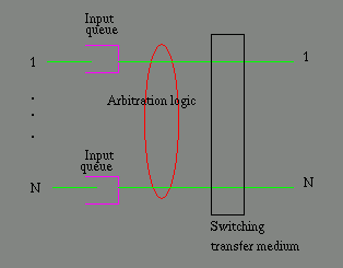
Input queueing: In this, the contention problem is solved at the input buffer of the inlet of the switching element. Each inlet contains a dedicated buffer which is used to store the incoming cells until the arbitration logic decides to serve the buffer. The switching transfer medium then switches the ATM cells from the input queues to the outlet avoiding an internal contention. The arbitration logic can be as simple as round-robin or can be complex such as taking into account the input buffer filling levels. However, this scheme has Head of Line(HOL) blocking problem i.e. if two cells of two different inlets contend for the same output, one of the cells is to be stopped and this cell blocks the other cells in the same inlet which are destined for different outlet. This queueing discipline can be shown by the following figure.

Output Queueing: In this queueing discipline, queues are located at each outlet of the switching element and the output contention problem is solved by these queues. The cells arriving simultaneously at all inlets destined for the same output are queued in the buffer of the outlet. The only restriction is that the system must be able to write N cells in the queues during one cell time to avoid the cell loss where N is the total no. of inlets of the switch.In this mechanism, no arbitration logic is required as all the cells can be switched to their respective output queue. The cells in the output queue are served on FIFO basis to maintain the integrity of the cell sequence. The following figure illustrates this mechanism.

Central Queueing: In this scheme, the queueing buffers are shared between all inlets and outlets. All the incoming cells are stored in the central queue and each outlet chooses the cells which are destined for it from this central memory. Since cells for different outlets are merged in this central queue, FIFO discipline is not followed in reading and writing of this queue. Cells can be written and read at random memory locations and this needs a complex memory management system for this scheme. The following figure shows this mechanism.

 Subway Map

 ATM Home Page